Technical Notes
For more information, refer to Ridley Engineering's Application Notes on analyzer measurements for power systems.
Impedance Measurements
The analyzer can measure impedance which includes the following applications:
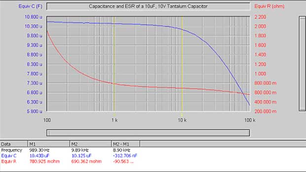
- Capacitance, the capacitor's ESR and the capacitance/ESR "zero" frequency
- Inductance of chokes and transformers including their resonant frequencies
- Input/output impedance of amplifiers and power supplies
For more information on impedance measurements for power systems see Ridley Engineering's application notes for the analyzer
Basic Impedance Measuring Setup
To measure the input or output impedance of a network, the analyzer is connected to a known reference resistor, R, that is in series with the network.
The source output and channel A are connected to one side of R and the other side of R is connected to channel B and the network under test as depicted below.
For best accuracy, the resistor R is chosen such that its impedance is within a factor of 5 or so of the expected impedance of the network under test, at the frequency of interest.
Complex Impedance Measurement Calculations:
Let the transfer function measured by the analyzer be H(f), the unknown complex impedance, Z(f)= x + j•y, is then given by: Z(f) = R•H(f)/(1-H(f)). This result is derived using the generalized voltage divider formula with the substitution of VB = H•VA.
First the magnitude of H(f) is converted from dB’s to linear form by dividing by 20 and taking the antilog (base 10). The phase is used directly as read from the analyzer taking care to include the sign. The converted magnitude along with the phase now represents H(f) in polar form, and is then converted to rectangular form and substituted into the formula above. The resulting complex number is the impedance in ohms and will typically have a real part, x, representing the equivalent series resistance, and a imaginary part, y, representing the equivalent reactance of the network under test. A capacitive reactance will have a negative imaginary part, while an inductive reactance will have a positive imaginary part. The equivalent capacitance is given by C = -1/(2•pi•f•y) and the equivalent inductance given by L = y/(2•pi•f) where f is the measurement frequency in Hz.
The impedance calculations derived above are done automatically by the software when the Complex Impedance option is chosen within the Graph menu.
- A choice of topologies allows the user to select a topology that best fits the measurement to be made.
- A choice of connection topologies are available for both high impedance networks and low impedance networks.
- A choice of display modes are available which give options on how the complex impedance data is formatted and displayed. The display modes include polar, rectangular and equivalent circuit with a parallel or serial topology being options.
Graph of the Capacitance and Equivalent Series Resistance of a 10uF Tantalum Capacitor as a Function of Frequency: